Input / Output Settings
Settings, IO tabs. On this page, the user can configure input and output settings.
Digital Inputs
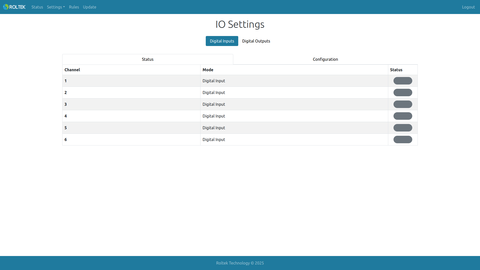
From the Digital Inputs tab, the user can observe the status of digital inputs from the
- Status tab or configure the inputs from the
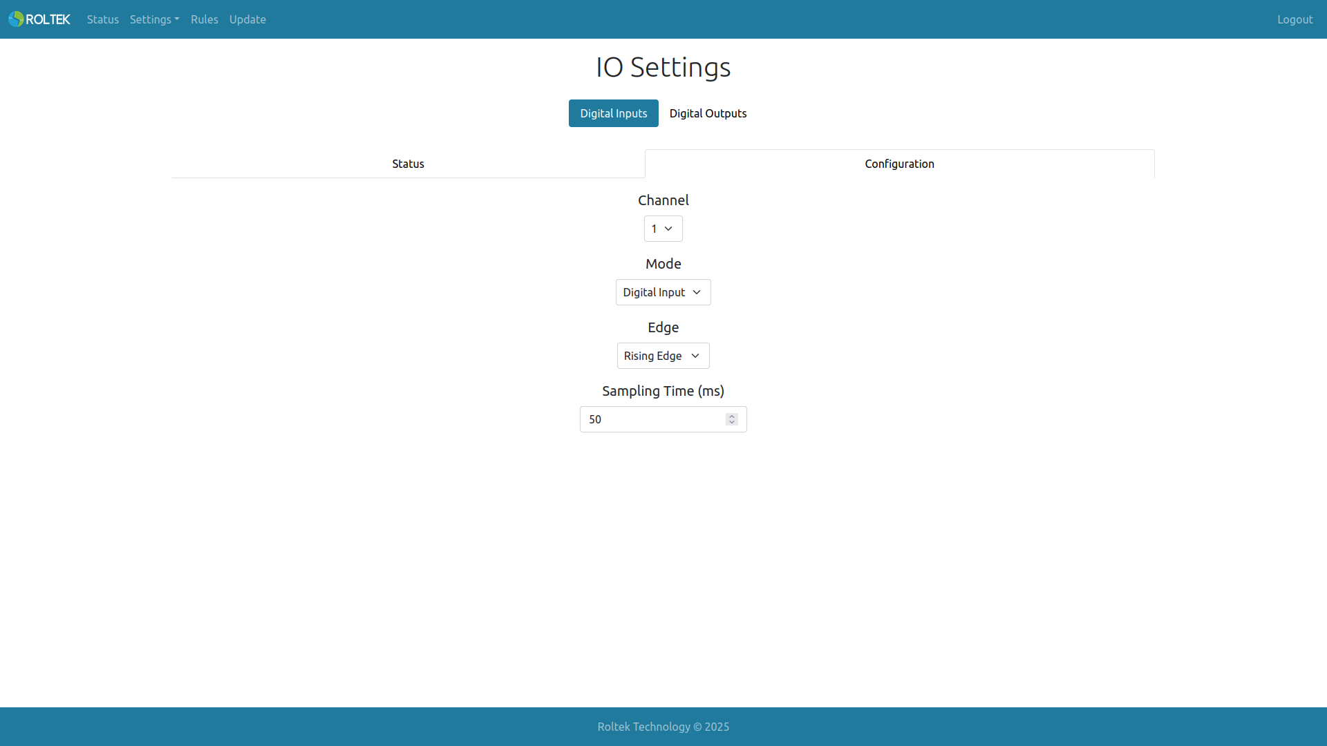
- Configuration tab.
If the input level is high or low, the corresponding part in the Status tab will be gray or green according to the configuration.
From the Configuration tab, the user can select which input to configure from Channel.
- If the Mode parameter of the digital input is selected as Digital Input
- The operation of the input can be determined by setting the Edge value. If Falling Edge is selected, the input value is high on the falling edge and low on the rising edge. If Rising Edge is selected, the input value is low on the falling edge and high on the rising edge.
- The Sampling Time value for the digital input can be set. If the value of the input signal does not change during this Sampling Time, this value is considered the valid input value.
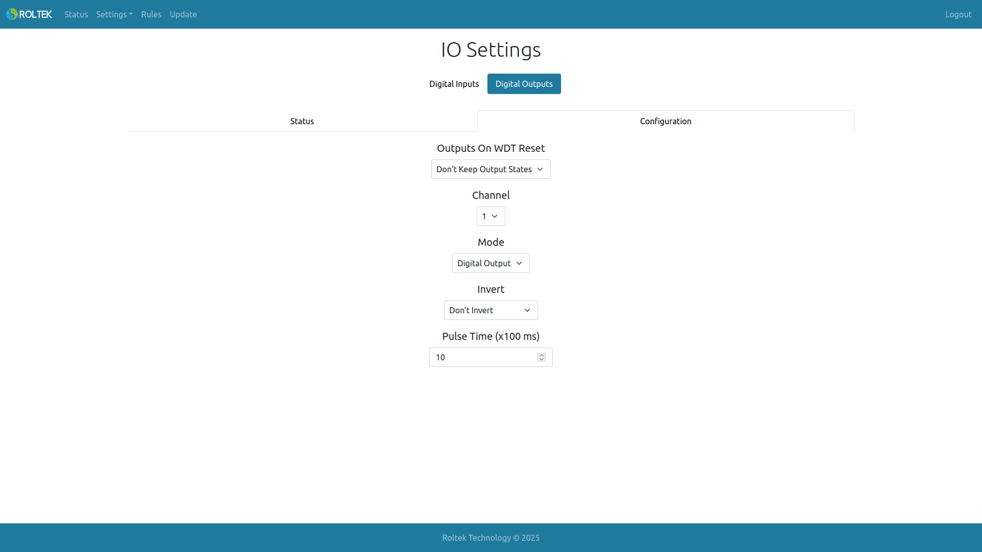
Digital Outputs
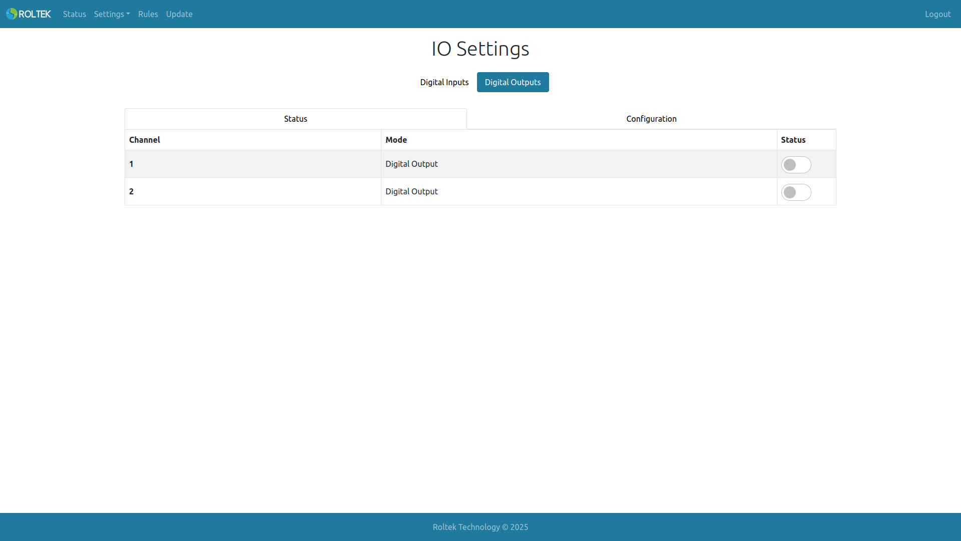
In the Digital Output tab, the user can change or observe the status of digital outputs from the
- Status tab or configure the outputs from the
- Configuration tab.
- From the Configuration tab, the user can select which output to configure from Channel.
- If Invert or Don't Invert is selected, the output value is high if the corresponding register (Out*Lock or Out*) value is high. This is also true for the opposite case.
- If Invert is selected, the output value is high if the corresponding register (Out*Lock or Out*) value is low. This is also true for the opposite case.
- Pulse Time: The Timeout value required to return the output value to its previous value (according to the Out*'s register value).