Sensor Probe Connection
Preparation
Sensor Probe
Have one of these sensors ready:
| Type | Sensor cable pin |
|---|---|
| RS485 Modbus-RTU | 1 x A, 1 x B, 1 x GND, 1 x VCC |
| 4 – 20 mA | 1 or 2 x signal pin |
| 0 – 10V | 1 or 2 x signal pin |
| Level | 1 x signal pin |
| Pulse Count | 1 x signal pin |
Note: Each Data logger can only connect to one type of sensor. For example:
- A single-address RS485 sensor
- A 4 – 20mA sensor with 1 or 2 measurements
- A 0 – 10V (below 10V) sensor with 1 or 2 measurements
- A pulse or level sensor with 1 measurement
Tools
| Type | Description |
|---|---|
| Star screwdriver | No.2 star tip |
Connecting the Sensor Probe
Removing the Data Logger
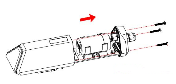
- Remove the three screws.
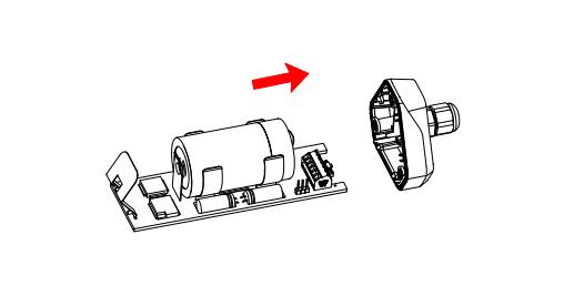
- Remove the cover.
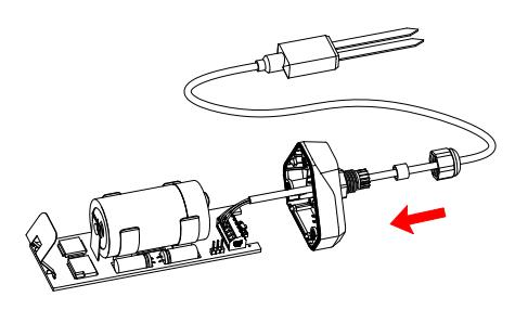
- Remove the screw head and pass the sensor cable through, through the bottom cover and connect it to the cable terminal.
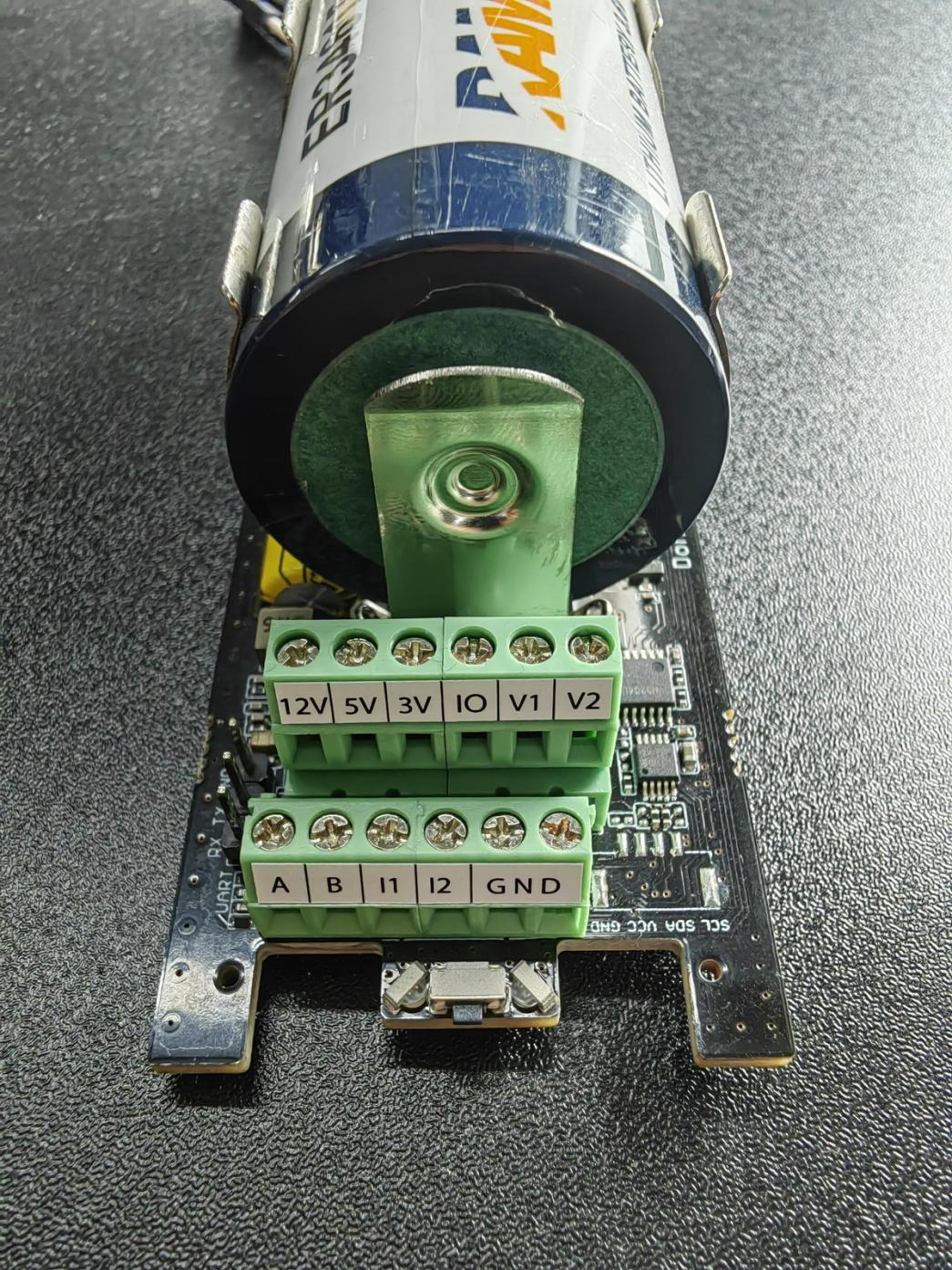
| No. | Pin | Description |
|---|---|---|
| 1 | 12V | External 12V input voltage. The Data Logger can be powered by an external 12V DC power supply. When a 12V power supply is used, the battery acts as a backup power source. |
| 2 | 5V | 5V output voltage, provides 5V voltage to the sensor. |
| 3 | 3V | 3V output voltage, provides 3V voltage to the sensor. |
| 4 | IO | Level or pulse input collection |
| 5 | V1 | Analog voltage input between 0 and 10V |
| 6 | V2 | Analog voltage input between 0 and 10V |
| 7 | A | RS485 A/+ |
| 8 | B | RS485 B/- |
| 9 | I1 | Analog current input between 4 and 20mA |
| 10 | I2 | Analog current input between 4 and 20mA |
| 11 | GND | Ground |
| 12 | GND | Ground |
Sensor Power Supply Options
The Data Logger supports two power supply modes:
| Mode | Description |
|---|---|
| Internal Battery | When the Data Logger and sensors are powered only by the internal battery. The data logger only supports 5V or 3V sensor probes. |
| External 12V DC | In some cases, the sensor probe requires a higher power supply that the internal battery cannot sustain for long periods. An external 12V power supply can be the main power source and the internal battery acts as a backup power source when there is a 12V power outage. When using an external 12V power supply, it is recommended to operate it with a junction box to ensure waterproofing. |
How to Set Up External 12V DC
When your sensor requires 12V power, the internal battery cannot power the sensor. Therefore, an external 12V power supply is required.
- Prepare the 12V DC adapter, junction box, and 4-pin cable.
- Connect RS485-A, RS485-B, GND, and external 12V input to the green terminal.
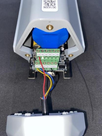
Cable description:
| Cable color | Data Logger pin |
|---|---|
| Red | 12V |
| Black | GND |
| Yellow | A |
| Blue | B |
- Place the device circuit board back into the enclosure and ensure that the waterproof rubber is correctly mounted.
- Connect to the terminal of the junction box.
- Connect the sensor cable to the junction box.
- Connect the 12V DC adapter to the power supply.
- Complete the assembly.
- Tighten the screws and screw heads to check for waterproofing. If the cable diameter is too thin, add waterproof tape to wrap it.
Note: When assembling the device, it is necessary to install the waterproof pad of the Data Logger and the adapter box and tighten the screw head and screw; otherwise, the waterproof effect of the device may be adversely affected! If the cable diameter is too small, it can be wrapped with waterproof tape.