Hardware Installation
Before powering on the device, follow the steps below:
- The power connection of the device is shown in the Power Connection section. Polarization is important in the power connection.
- The serial port communication of the device is shown in the RS485 Connection section. Incorrect connections in communication ports can cause permanent damage to the devices. Please check the connections carefully and ensure that they are made correctly.
- To use the optically isolated digital inputs on the device, you need to apply 10-26VDC to the device input. An example connection diagram is shown in the Digital Input Connection section.
- The relay outputs on the device have normally open (NO) terminals. In cases where high power is required, it is recommended to use these outputs with external relays or contactors. An example connection diagram is shown in the Digital Output Connection section.
After this step, ensure that all cable connections are as shown in the provided diagrams and then power on the device.
If the connection is correct, the power LED will light up.
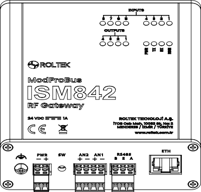
Front View
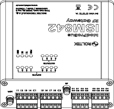
Back View