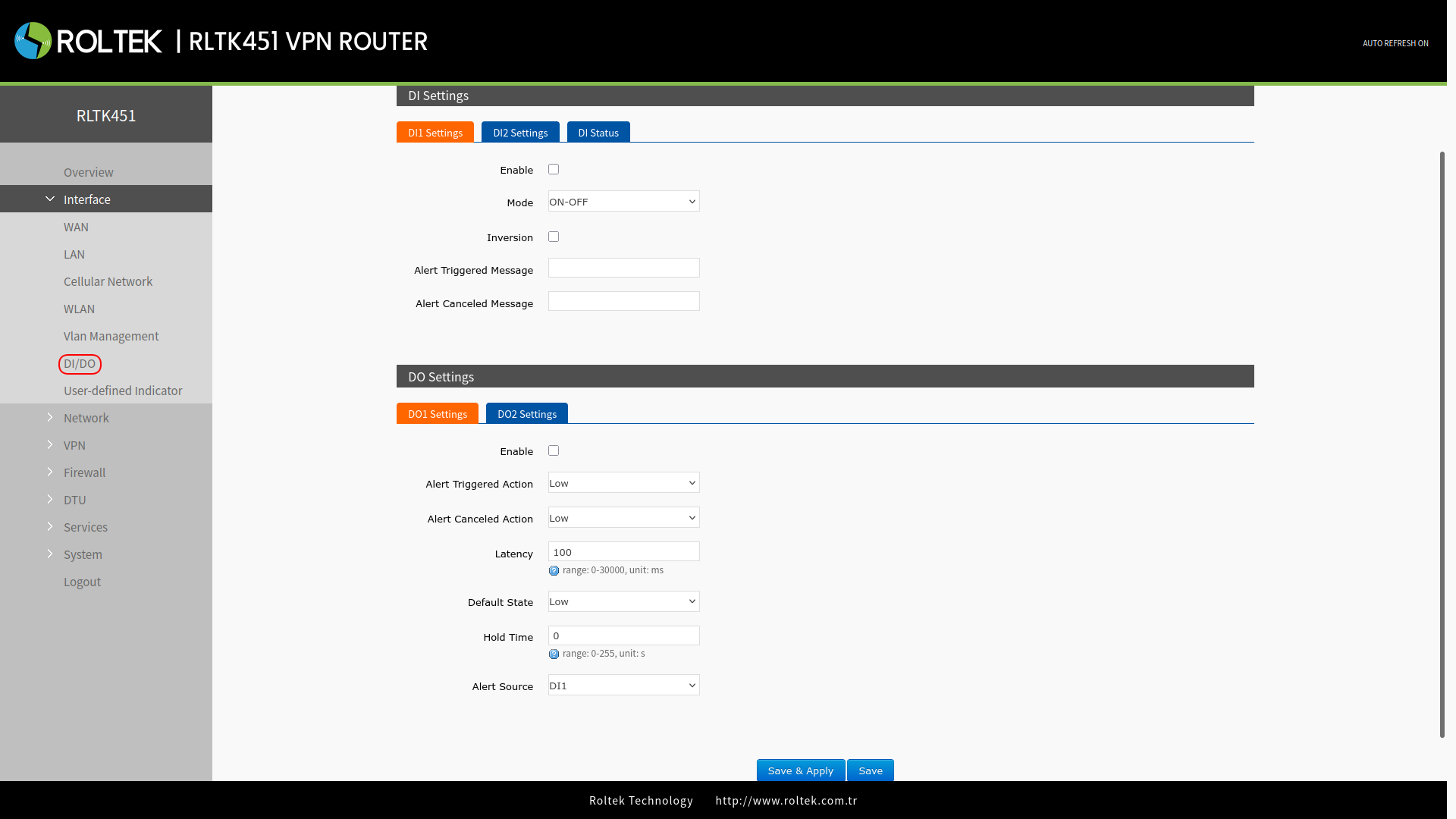
Digital Input/Output Settings
The RLTK451 has two digital inputs (DI) and two digital outputs (DO). DI can be used to trigger alarms; DO can be used to control the device based on the triggering condition. To access the settings:
- Follow the menus
- Interface
- DI/DO
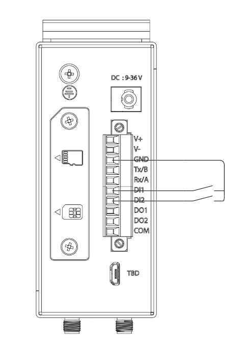
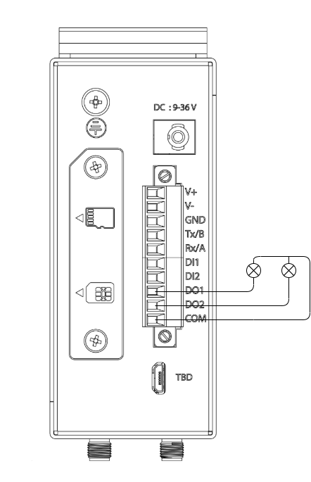
Hardware Connection Diagram
Digital Input Connection
2x DI: Can operate as a dry contact, voltage-free contact, or a regular ON/OFF switch. It is non-polarized and can be adapted to different wiring.
Digital Output Connection
2x DO: Can operate as a wet contact, active contact, or controlled switch. It has polarity and the wiring cannot be reversed.
Digital Input Settings
Digital input 1 can be configured through DI1 Settings, and digital input 2 can be configured through DI2 Settings.
| Parameter | Description | Default Value |
| Enable | Enable/disable the digital input. | Disable |
| Mode | ON-OFF: The input operates logically high/low, triggering the alarm with its logical level. Counter: The input operates as a counter. Rising edges trigger counting. | ON-OFF |
| Inversion | If selected: In ON-OFF mode, it triggers an alarm on low logic. In Counter mode, it counts falling edges. | Not selected |
| Alert triggered message | The alarm message to be sent when the input is triggered. | |
| Alert canceled message | The message to be sent when the input trigger ends. |
The status of the inputs and the total counted value, if set as a counter, can be observed through DI Status.
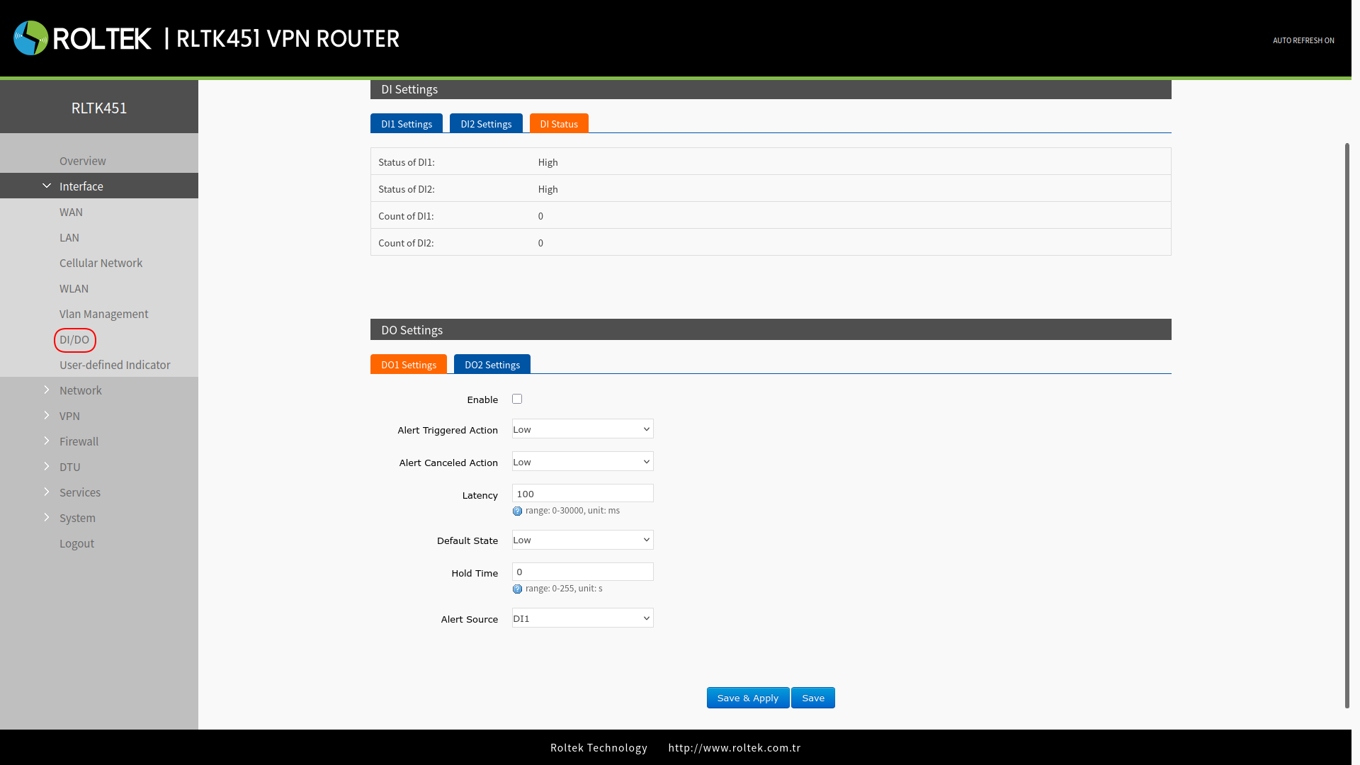
Digital Output Settings
| Parameter | Description | Default Value |
| Enable | Enable/disable the digital output. | Disable |
| Alert triggered action | Can be set to High, Low, or Pulse. Specifies the action the output will take when the alarm is triggered. | Low |
| Alert canceled action | Can be set to High, Low, or Pulse. Specifies the action the output will take when the alarm trigger ends. | Low |
| Latency (Unit: ms) | Specifies how long the output will wait before taking action after the alarm. Can take a value between 0 - 30000 ms. | 100 |
| Default state | The default value of the output. Can be High (logical high) or Low (logical low). | Low |
| Hold time (Unit: s) | The duration for which the output will hold the action, valid only if High (logical high) or Low (logical low) is selected. 0 means until the next action. Other values determine the duration of the action. Can take a value between 0 - 255 s. | 0 |
| Low level width (Units: s) | Valid if Alert triggered action is selected as Pulse. The pulse low logic duration of the output can be set to a value between 0 - 30000 ms. | 1000 |
| High level width (Unit: s) | Valid if Alert triggered action is selected as Pulse. The pulse high logic duration of the output can be set to a value between 0 - 30000 ms. | 1000 |
| Alert source | Can select DI1 or DI2 as the alarm source that will trigger the output. | DI1 |